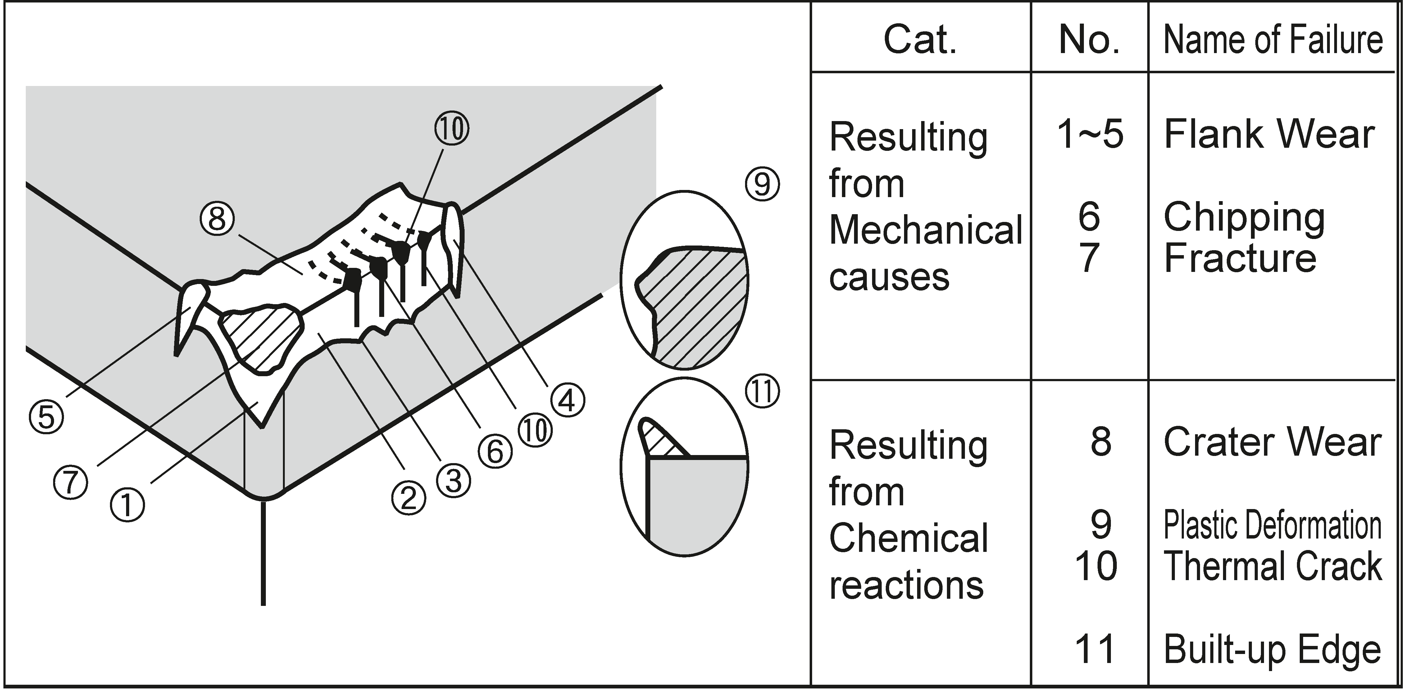
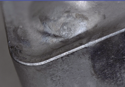
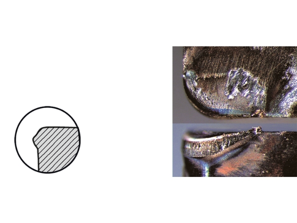
Characteristics:
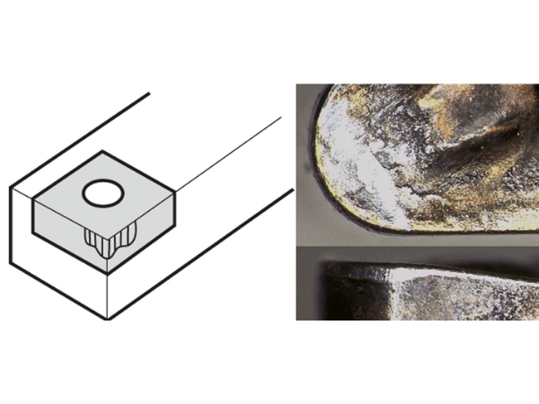
A continuous wear zone along the clearance face of the insert
Typically occurs during long-term, uniform wear processes
Often the main tool life criterion, as it develops gradually
Cause:
Abrasive wear due to hard particles in the workpiece
High cutting speeds intensify the effect
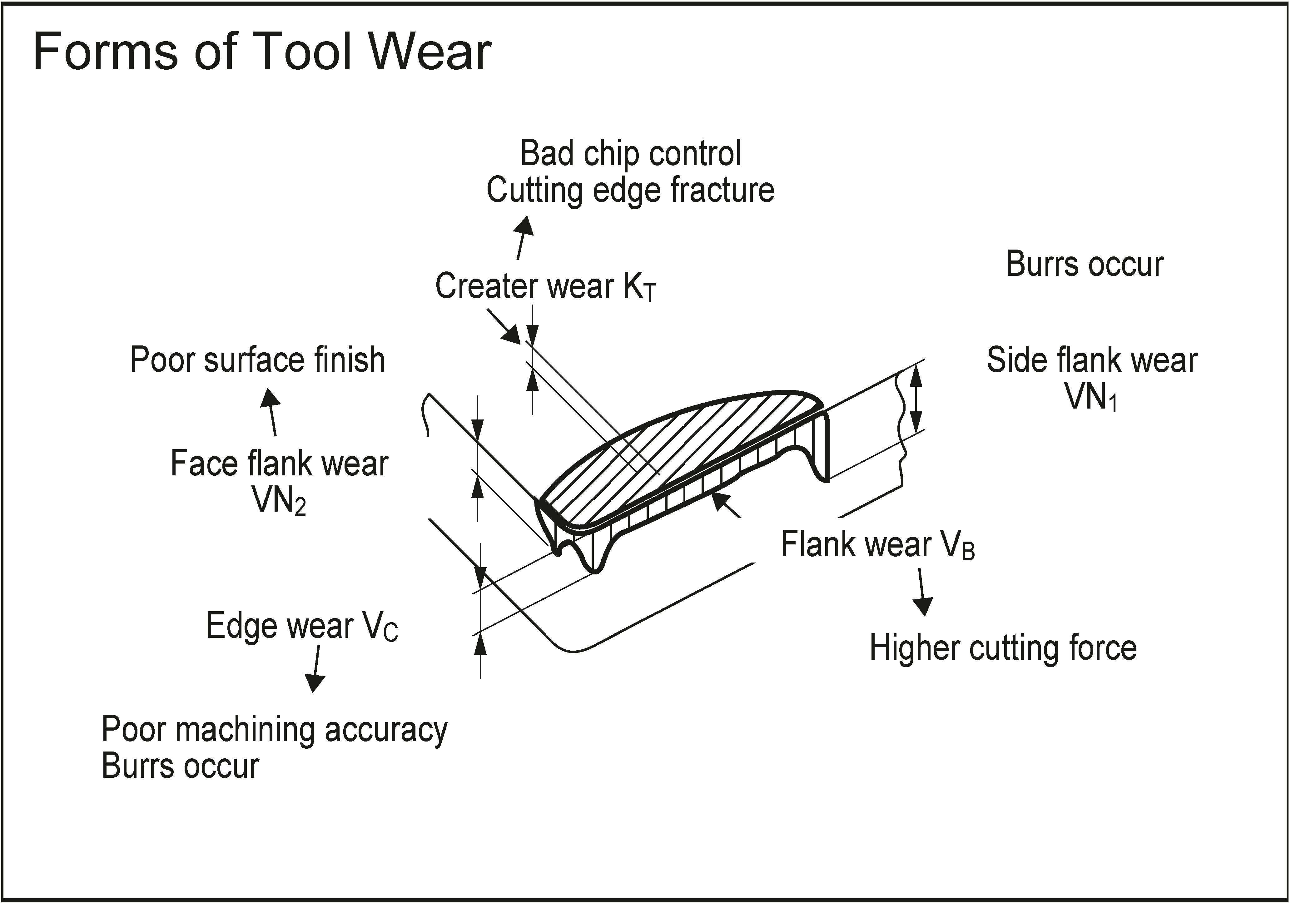
Consequences:
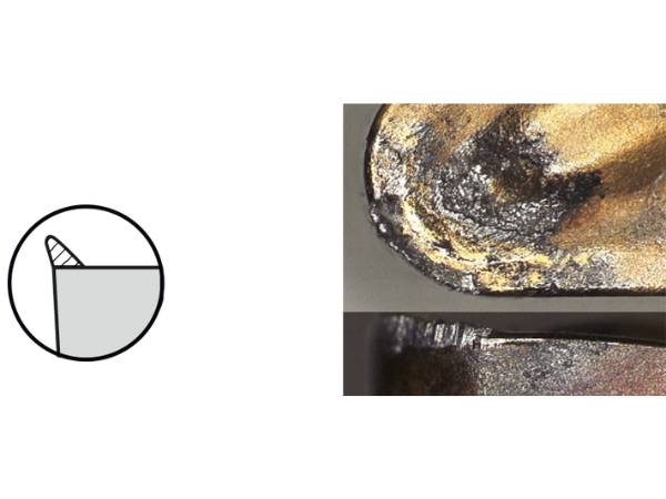
Dimensional inaccuracies and reduced surface quality
Increased cutting forces and heat generation
Solution:
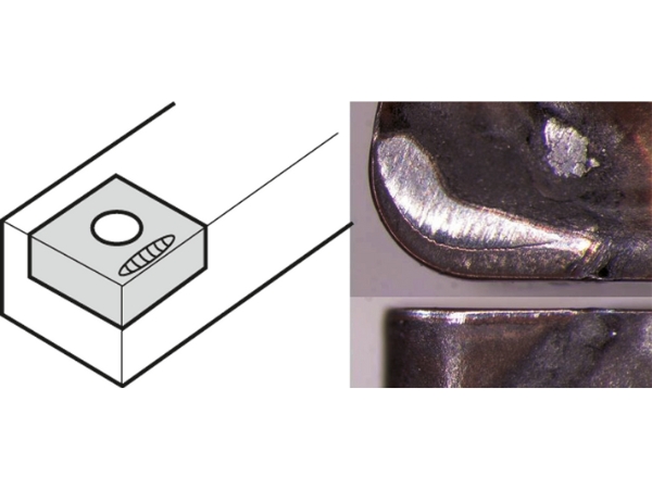
✔ Use harder or coated inserts
✔ Lower cutting speed, increase feed rate if appropriate
✔ Select the correct cutting edge geometry
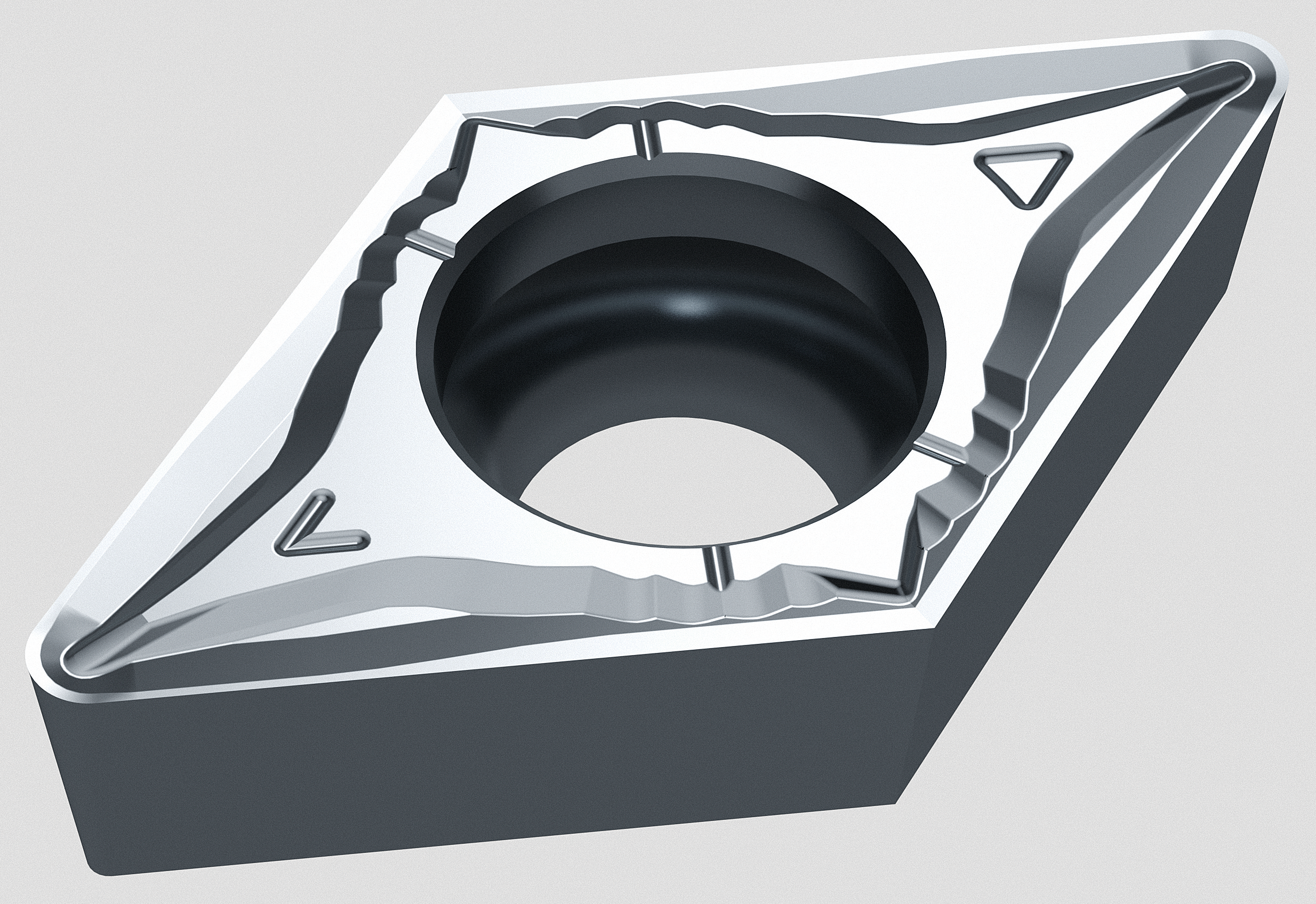
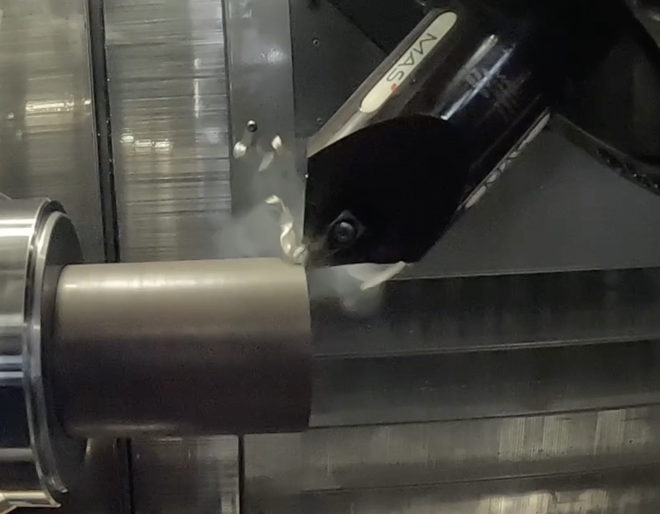
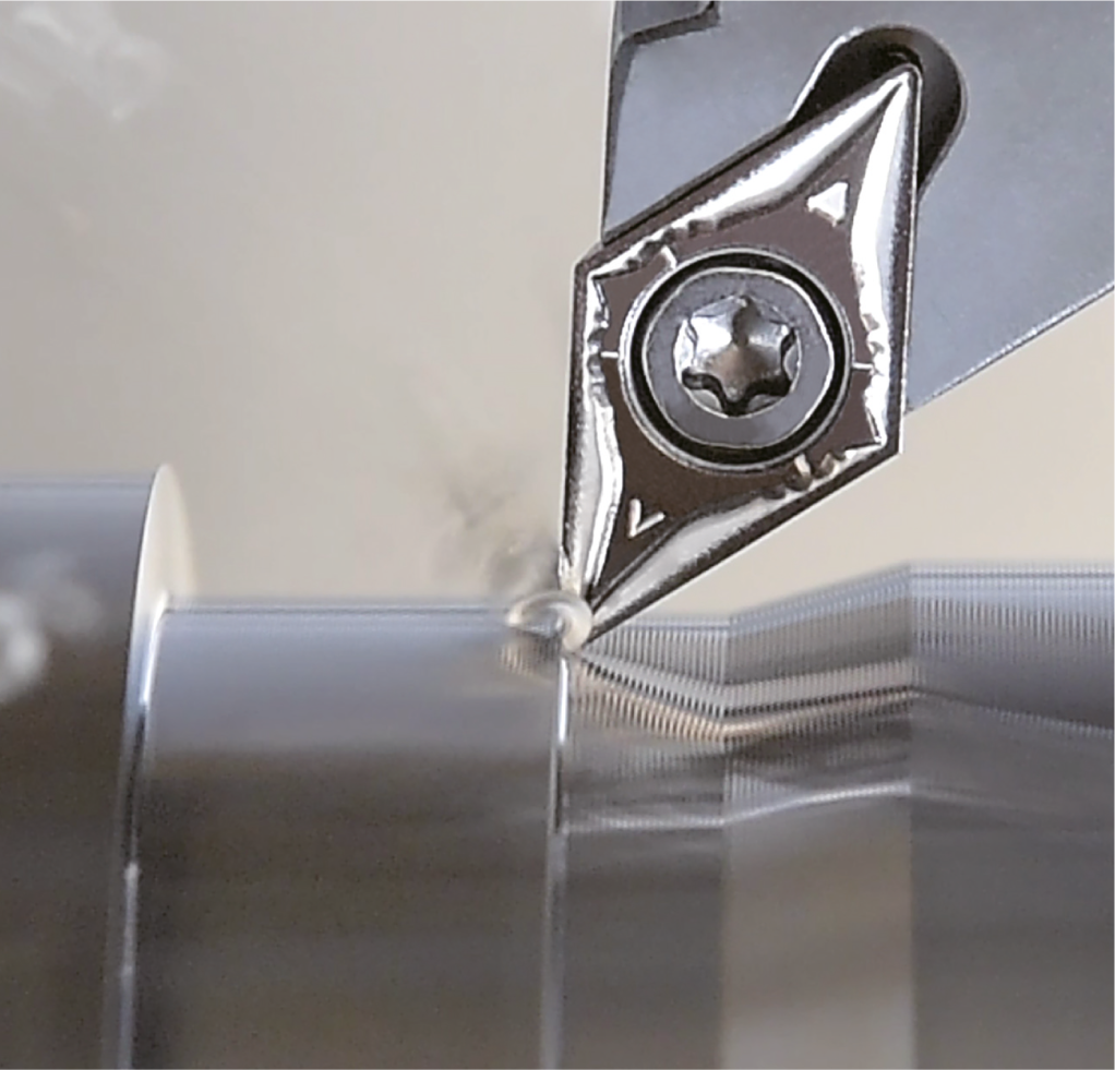
Flank wear is especially problematic in internal machining, where slender tools with long overhangs are used. This increases the risk of vibrations caused by flank wear.
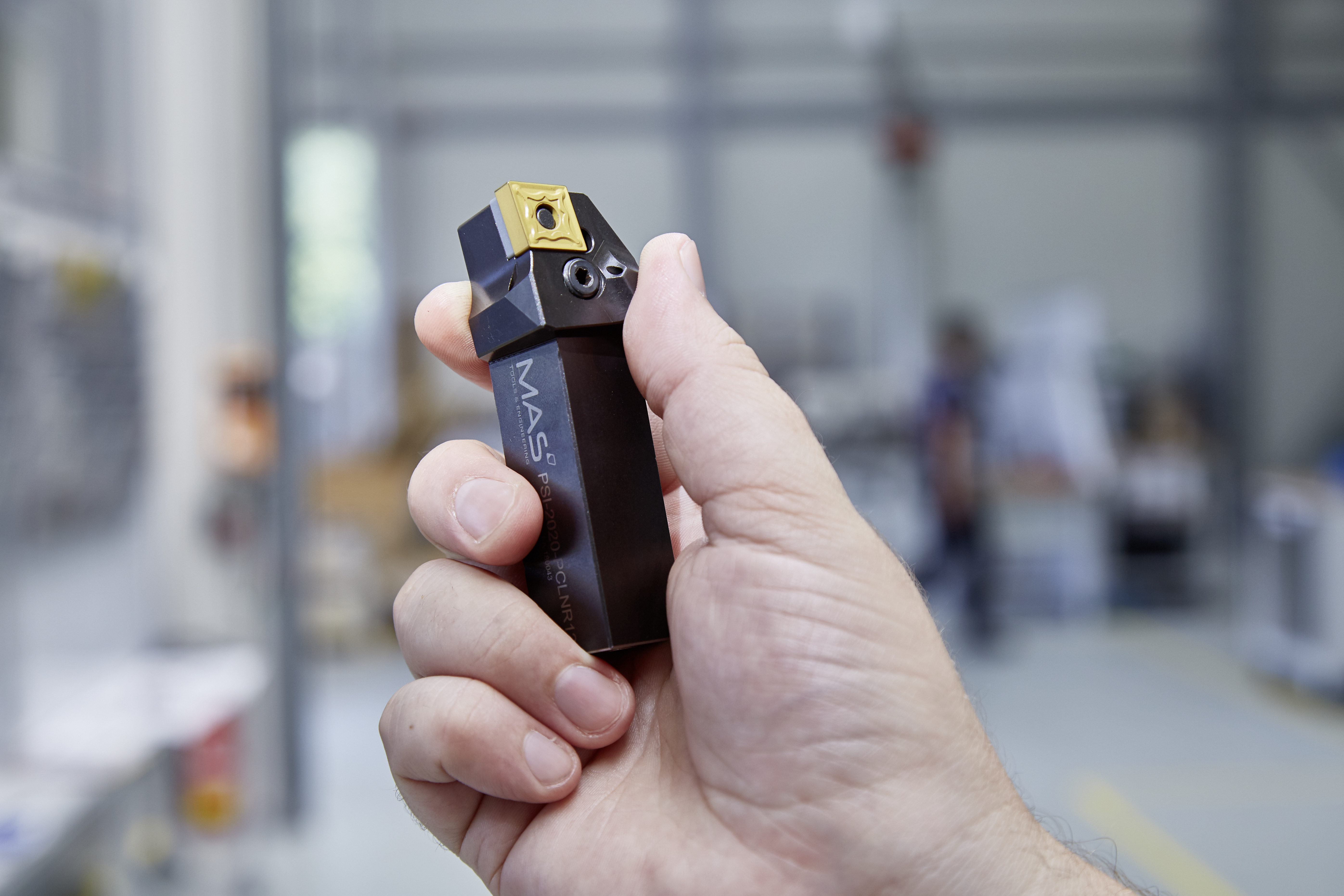
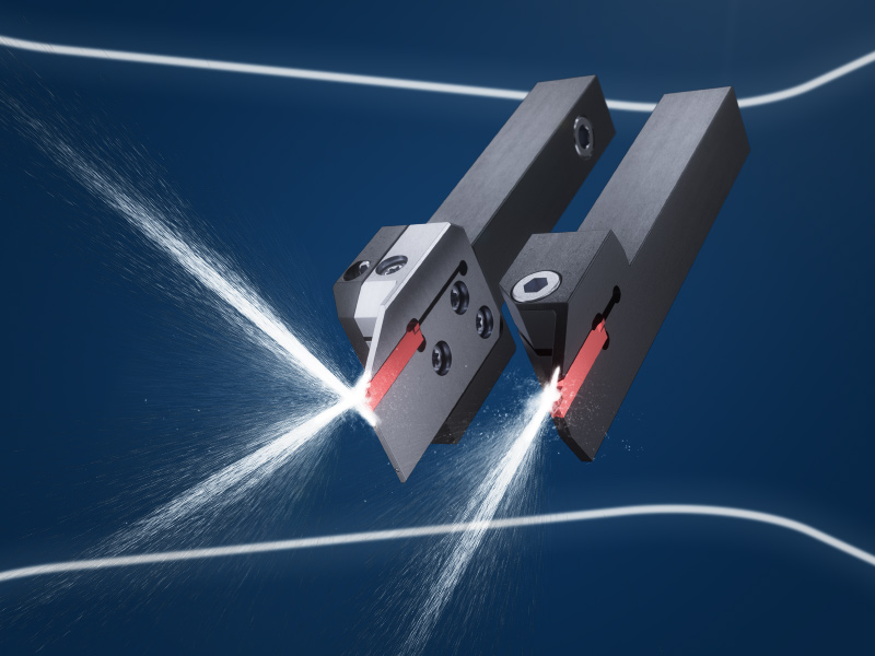
The IN©turn system from MAS features a cutting edge geometry optimized for both sharpness and edge stability. Combined with a high-performance coating, this reduces cutting forces and thus friction on the clearance face.