Chip control in machining: Understanding chips, optimizing processes
Those who understand chips and influence them in a targeted manner can significantly optimize the machining process.
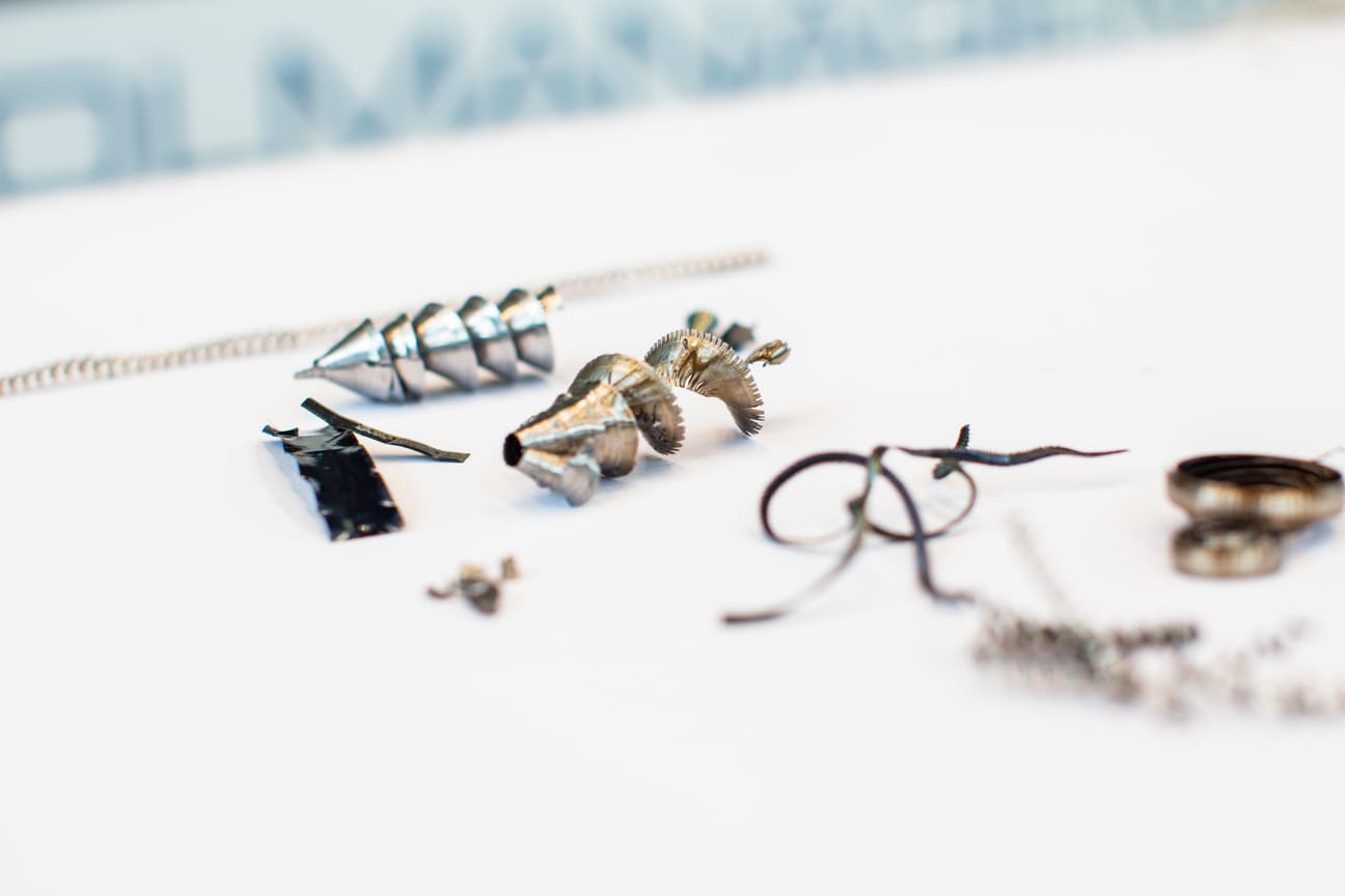
Chips are an unavoidable by-product of machining technology—and at the same time a decisive factor for process reliability, tool life, and the quality of the machined workpiece. Their shape, size, and composition influence not only the efficiency of production, but also aspects such as tool wear, safety risks, and disposal costs. Understanding chips and influencing them in a targeted manner can significantly optimize the machining process.
In most cases, an ideal chip should:
In practice, however, chip control is a challenge, as many factors—from tool geometry and cutting parameters to coolants—influence chip formation.
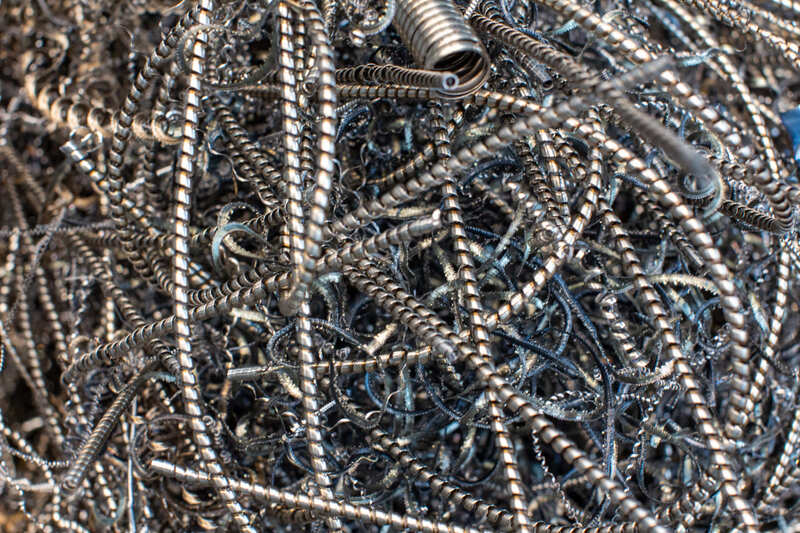
Uncontrolled or unfavorable chips can cause significant problems in the machining process and negatively impact the entire production process.
Long, uncontrolled chips can wrap around the tool or workpiece, leading to machine downtime and compromising workplace safety. Chips that are too short and hard can lead to increased tool wear and unstable cutting conditions, which in turn promote chatter marks. But chips left behind on the part surface can also cause scratches or dimensional deviations.
The most important problems are summarized in the following table:
| Problem Category | Causes | Effects |
| Process reliability | - Long chips wrap around the tool/workpiece - Chips clog machine areas | - Machine downtime - Chip wrapping leads to tool breakage |
| Tool life | - Hard, short chips cause micro-impact - Build-up edge formation due to adhesive materials | - Faster cutting edge damage - Higher tool wear |
| Machining quality | - Chips remain on workpiece surface - Chip residues between tool and workpiece | - Scratches & surface defects - Dimensional deviations |
| Chip disposal & recycling | - Chips contaminated with cooling lubricant - Combustible chips (magnesium, titanium) | - Complex separation and disposal - Increased fire hazard |
| Occupational safety | - Flying chips - Sharp-edged chips during handling | - Risk of injury - Health risks due to dust particles |
Avoid costly machine downtime, improve process reliability, and optimize chip removal with customized chip control. We analyze your machining process and help you to specifically influence chips and increase the efficiency of your production.
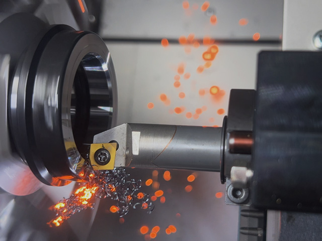
Chip formation is a complex physical process determined by the interaction of the cutting tool, workpiece, and machining parameters.
A chip is formed when the cutting wedge penetrates the material during machining, causing it to deform elastically and plastically. As soon as the material's load limit is exceeded, it flows into a so-called shear zone, where it is finally separated. This generates temperatures of several hundred degrees Celsius, which significantly influence the material properties and chip breakage.
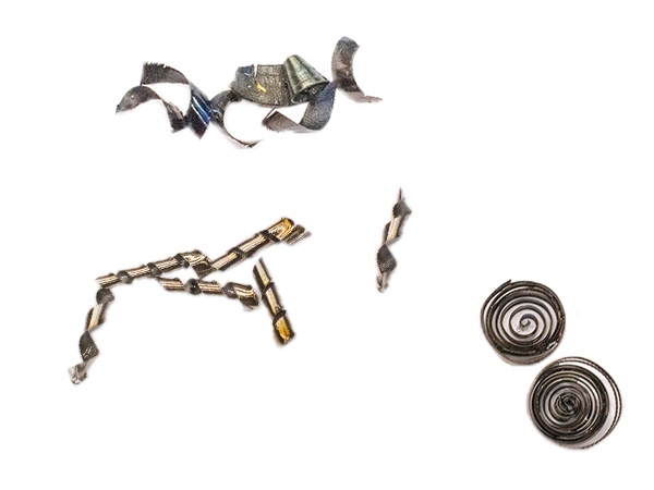
Chips can be divided into different categories based on their shape and structure. The chip shape depends heavily on the material, the cutting conditions, and the tool geometry.
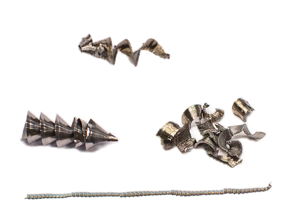
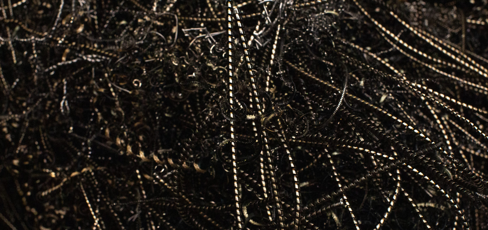
Chip shapes are generally divided into three groups: unfavorable, acceptable, and good. The goal is to achieve a chip shape that is easy to remove, does not negatively affect tool life, and does not cause machine problems.
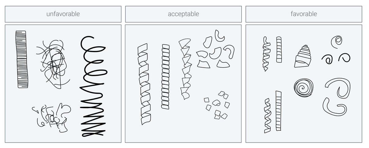
These chips can wrap around the tool, damage the cutting edge, or lead to poor surface finishes on the workpiece. They take up a lot of space, interfere with machine operation, and pose safety risks:
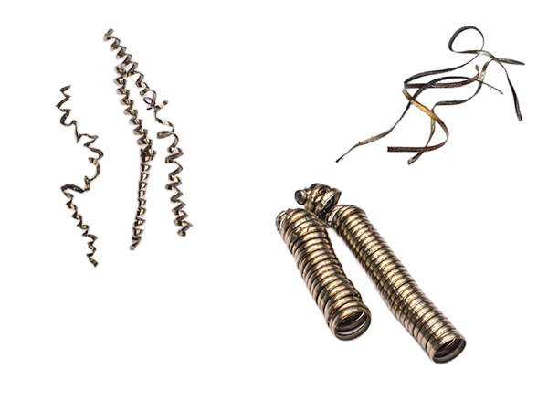
Some chip forms are not ideal but are acceptable under certain conditions. They cannot always be completely avoided in specific machining processes, but they do not pose an immediate problem.
These types of chips occur primarily when machining aluminum or stainless steel and can be controlled by adjusting the cutting parameters.
Ideal chip forms can be easily evacuated from the machining area, reduce the risk of chip entanglement, and improve tool life.
These chip forms typically occur under optimal cutting conditions, for example through correct tool geometries, optimized feed rates, and effective chip breaker geometry.
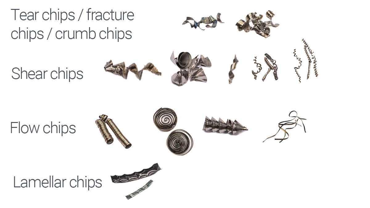
In addition to the external shape, chip types are also distinguished. They describe the internal structure of the chip and the mode of shearing:
Targeted adjustment of tool geometry, cutting parameters, and coolant application can help avoid problematic chip forms and optimize the process.
The main factors influencing the chip formation are:
Workpiece material
Different materials to be machined play a decisive role, as even steels and cast irons differ depending on their carbon content, alloying elements, or heat treatment condition. Even small variations in alloying elements can lead to the formation of long or short chips.
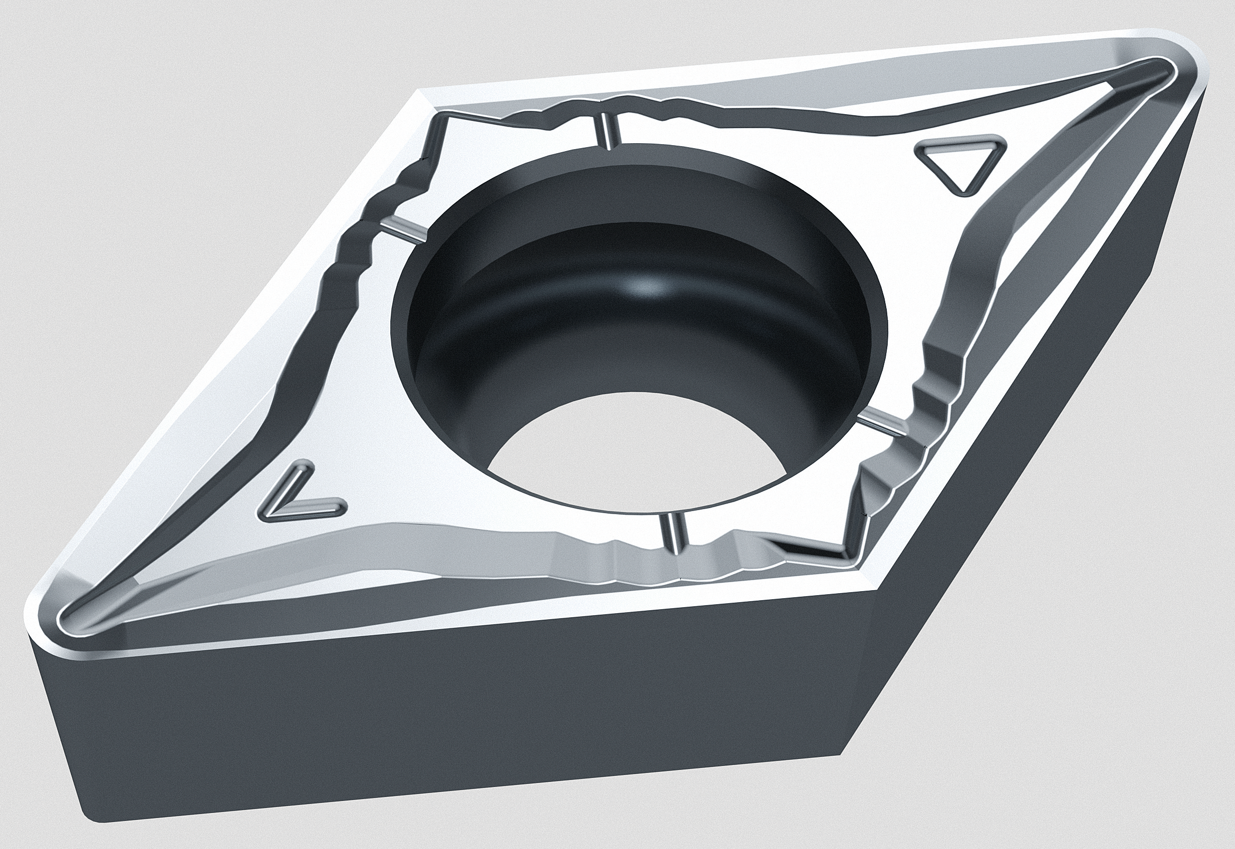
Tool geometry
This includes rake angle, corner radius, cutting edge preparation, and chip breakers, all of which determine how the chip is formed and broken.
Cutting conditions
Feed rate, cutting speed, and depth of cut define the load acting on the tool and the workpiece. In interaction with the depth of cut, the tool manufacturer specifies the optimal application range for the tool.
Coolants and lubricants
They influence the temperature in the machining process and can positively affect chip formation through cooling and lubrication.
| Material | Tendency in chip type |
|---|---|
| Brittle materials (e.g. cast iron) | Crumb chips (formed by material break-out, resulting in a rough surface) |
| Hardened steels | Short or long chips (strongly dependent on the specific material) |
| Medium-strength steels | Shear chips |
| Ductile materials (e.g. aluminum) | Flow chips (continuous chip flow, requires effective chip control) |
| Low-alloy steel | Flow chips (without suitable chip breakers, chips can become very long and problematic) |
| Materials with inhomogeneous microstructure | Lamellar chips (caused by variations in chip thickness) |
| ISO group P (steel) | Long chips (special chip control measures required) |
| ISO groups K (cast irons) & H (hardened steels) | Short chips (chip control is usually easier) |
| ISO groups M (stainless steel), S (superalloys) & N (non-ferrous metals) | Highly dependent on alloying elements |
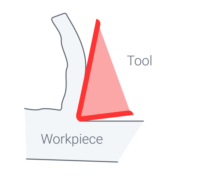
Influence of tool geometry on chip formation
Tool geometry plays a decisive role in machining, as it directly influences chip formation, cutting forces, heat generation, and ultimately the quality of the machined surface. Targeted adjustment of tool geometry allows the machining process to be optimized and chip form to be controlled effectively.
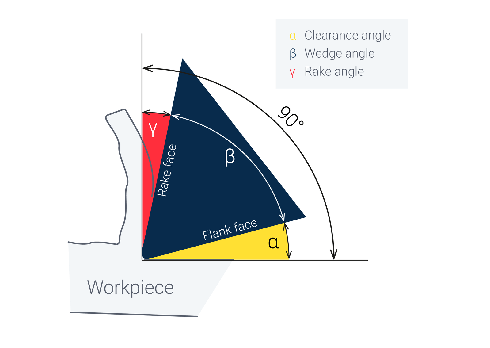
The cutting wedge geometry of a tool—consisting of clearance angle (α), wedge angle (β), and rake angle (γ)—largely determines how a material is cut and which type of chips are produced. It has a significant influence on chip form, chip breaking behavior, chip evacuation, and cutting forces.
The clearance angle ensures that the flank face of the tool does not rub against the workpiece and that only the cutting edge is actively engaged in cutting.
Large clearance angle (10–15°):
Small clearance angle (6–10°):
The wedge angle describes the material thickness of the cutting edge and directly affects how the chip is separated from the workpiece.
Large wedge angle (> 70°):
Small wedge angle (< 60°):
The rake angle determines the direction in which the chip is guided and therefore has a direct effect on chip form:
Positive rake angle (> 0°):
Neutral rake angle (~ 0°):
Negative rake angle (< 0°):
In addition to cutting wedge geometry, further factors such as the approach angle, cutting edge rounding, and inclination angle play a decisive role in chip formation. These extended geometry parameters influence the direction, shape, and stability of the chip and must be deliberately adapted to the workpiece material and the specific machining situation.
It is important to note that the optimal values for approach angle, corner radius, and inclination angle depend heavily on the specific application, including the workpiece material, the machining operation, and the desired surface properties.
| Parameter | Characteristic | Influence on chip formation |
|---|---|---|
| Approach angle (κ) | Small (< 90°) | Produces wider, thinner chips; can make chip control more difficult and promote long chips |
| Large (≈ 90° or greater) | Promotes controlled chip formation with shorter, more stable chips; reduces the risk of chip entanglement and improves chip evacuation | |
| Cutting edge rounding (corner radius) | Large corner radius (> 1 mm) | Increases chip compression; can hinder chip breaking, leading to long chips |
| Small corner radius (< 0.8 mm) | Facilitates chip breaking, promotes fine chip formation, and produces short chips | |
| Inclination angle (λ) | Negative inclination angle (< 0°) | Increases chip resistance, promotes stronger chip breaking, reduces long chips, and improves chip break control |
| Positive inclination angle (> 0°) | Promotes free chip flow and easier evacuation, but may cause long, problematic chips |
Chip formers are special geometrical features on the rake face of a tool that deliberately influence the shape, length, and breaking behavior of the chip. They play a crucial role in preventing long, problematic chips that could wrap around the tool or interfere with the machining process. Especially when machining ductile materials such as steel, aluminum, or stainless steel, chip formers are essential to ensure controlled chip evacuation.
Chip formers can be broadly classified into three main types, which are used depending on the material, cutting conditions, and the desired chip form:
| Chip former type | Resulting chip form | Advantages | Disadvantages |
|---|---|---|---|
| Open chip formers | Flow chips | Low cutting forces, good surface finish | Risk of long chips |
| Closed chip formers | Short or crumb chips | High process reliability, no chip entanglement | Higher cutting forces |
| Variable chip formers | Material-dependent | Flexible, adaptable to different conditions | More complex tool manufacturing |
A chip former influences the chip formation process already in the shear zone by deliberately deflecting the chip or breaking it through mechanical stress. Chips are either shortened, formed into spirals, or segmented into small pieces.
The most important mechanisms of chip control are:
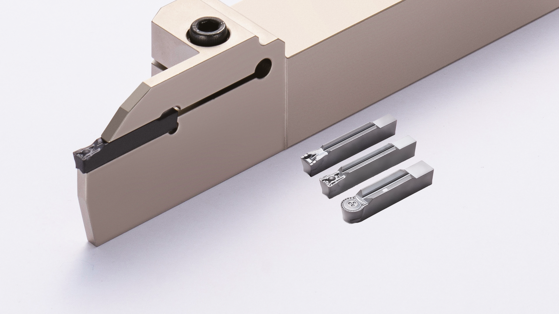
The GND series offers advanced grooving and parting tools with optimized chip-forming technology. It reduces vibration, improves chip control, and increases productivity through innovative geometries and internal coolant supply.
Reduced vibration – up to 30% less compared to conventional tools
High rigidity – for greater process reliability and longer tool life
Optimized chip evacuation – through targeted cooling and innovative chip breakers
Increased machining performance – for maximum efficiency when machining difficult materials
Cutting conditions are a key factor in chip formation, as they determine how the tool interacts with the workpiece. They include cutting speed (vc), feed rate (f), and depth of cut (ap). These parameters influence chip form, chip breaking behavior, and the stability of the machining process.
Choosing the correct cutting parameters is essential for efficient chip formation. A high cutting speed combined with a controlled feed rate can help avoid long, problematic chips. The depth of cut affects chip size and the overall stability of the machining process. By carefully adjusting these parameters, chip formation can be optimized and process reliability increased.
| Cutting parameter | Low value | High value |
|---|---|---|
| Cutting speed (vc) | Long, continuous chips, high tendency to chatter | Shorter chips, increased heat generation, reduced chip thickness |
| Feed rate (f) | Thin flow chips, risk of chip entanglement | Thicker chips, improved chip breaking, higher tool load |
| Depth of cut (ap) | Thin, long chips, reduced cutting forces | Large, voluminous chips, increased heat generation |
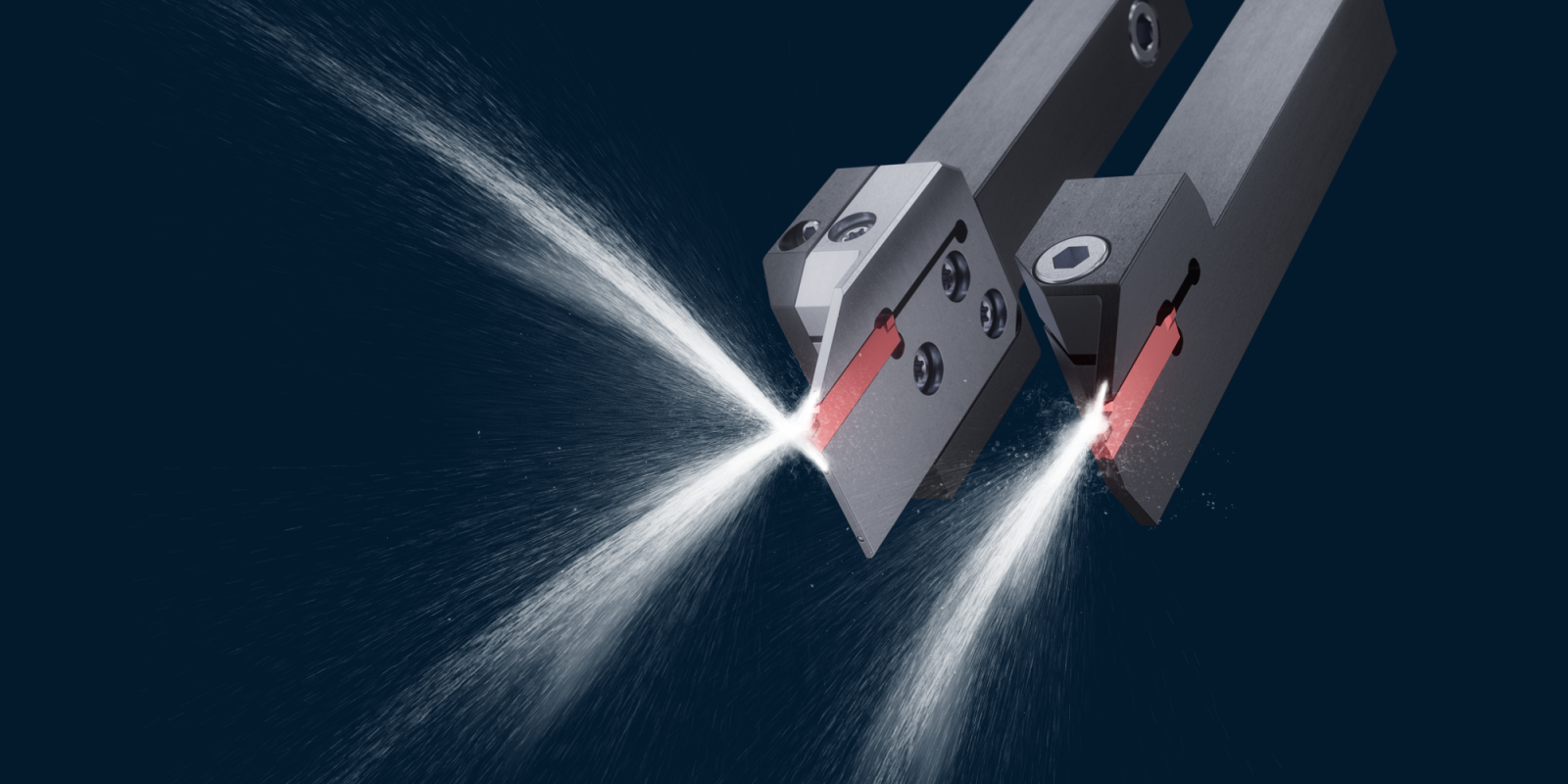
Coolants and lubricants (CL) are an essential component of the machining process and have a significant impact on chip formation, chip evacuation, and tool life. Their primary functions are to dissipate generated heat, reduce friction, and efficiently remove chips from the machining area.
The targeted use of coolants and lubricants has a direct influence on chip form, chip breaking behavior, and chip evacuation. High-pressure cooling improves chip evacuation when machining difficult materials, while well-controlled lubrication promotes targeted chip breaking and reduces tool wear. Selecting the right CL strategy therefore makes a major contribution to process reliability and machining efficiency.
| CL supply method | Effect on chip formation | Typical applications |
|---|---|---|
| Flood cooling | Uniform cooling, improved chip breaking, reduced friction | General machining, cast iron machining |
| Internal cooling | Effective heat dissipation, improved chip evacuation | General machining, deep-hole drilling, deep grooving |
| High-pressure coolant (HPC) | Promotes controlled chip breaking, prevents chip entanglement | Superalloys, stainless steel |
| MQL (minimum quantity lubrication) | Reduced friction, less heat buildup compared to dry machining | Aluminum, non-ferrous metals, conventional steels, stainless steels |
Modern manufacturing technologies increasingly rely on innovative solutions to avoid long, problematic chips, extend tool life, and improve process reliability.
New developments in tool geometries, digital monitoring systems, and alternative machining methods offer significant optimization potential.
Modern tool geometries are specifically designed to influence chip form. Advanced chip formers with variable breaking structures enable controlled chip segmentation and facilitate chip evacuation.
Especially when machining difficult materials, innovative coatings reduce friction and minimize chip adhesion. Dynamic cutting edges with optimized rake angles guide chips in a controlled manner to prevent long ribbon chips.
At the same time, digitalization is revolutionizing chip control. Sensors on tools and machines capture real-time data on vibration, temperature, and cutting forces to detect deviations at an early stage. With the help of artificial intelligence, this information can be analyzed so that machines automatically adjust cutting parameters. This not only optimizes chip formation, but also extends tool life and reduces scrap.
Our experience shows that those who optimally align material, tool geometry, cutting conditions, and coolant application gain decisive competitive advantages. Effective chip control is therefore not only a contribution to process reliability, but also a pathway to higher productivity and improved component quality. As a partner to the machining industry, we continuously develop new solutions to control chips efficiently—for more precise, economical, and sustainable manufacturing.